UNMANNED TECH
  • Home
  • Shop
  • Students/Researchers
  • About
  • Contact
  • Manuals
  • Regulations
  • Multicopter Safety Notes
  • Blog

3DR Radio v2 Quickstart Guide

6/11/2013

Comments

 
Picture
The 3DR Telemetry Radios provide an air-to-ground data link between the autopilot and your ground station laptop or tablet.  This guide will show you how to to install the radios on your plane, copter, or rover.  The Telemetry Kit arrives ready to use. Just mount and connect to view real-time data from your drone.  This telemetry kit is compatible with the ardupilot platform, as well as the PX4/Pixhawk system.

Buy 433mhz Telemetry Kit

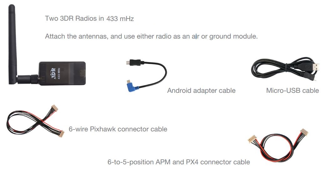
Parts INCLUDED with the 433Mhz 3DR TELEMETRY Kit
Picture

Connecting the Radios to your autopilot

ArduPilot
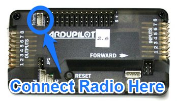
  • Connect to the APM 2.5 or 2.6 telemetry port using 2.6 the 6-to-5-position cable
PX4
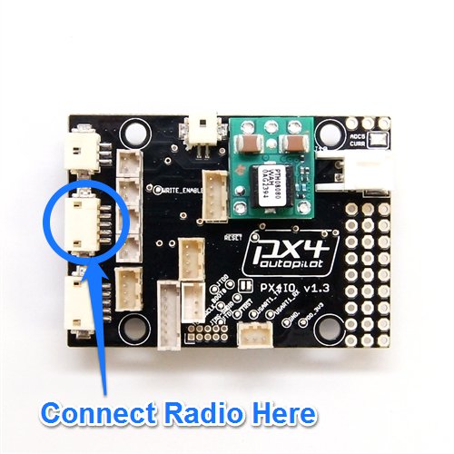
  • Connect to the PX4 I/O telemetry port using the 6-to-5-position cable.
PixHawk
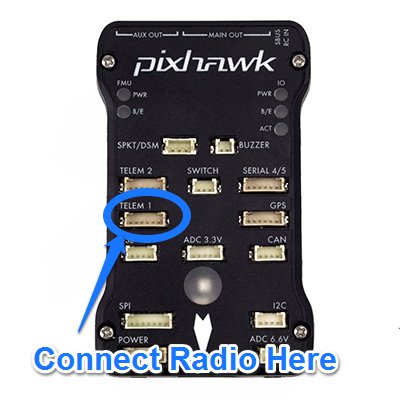
  • Connect to the Pixhawk telemetry port 1 using the 6-wire cable.

Mounting the Radio Module

Once the radio module is connected to your autopilot, you will need to now secure it to your aircraft.  Make sure to keep the antenna clear of any propellers or moving components.  Its best to orient the antenna vertically for best range/signal.

Connecting to Mission Planner (PC/Laptop)

Picture
Picture
  • The first thing to do is to download the missing planner software if you have not done so already, you can get it here.
  • The drivers for the radio module will be installed with the mission planner software.
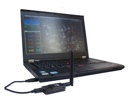
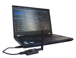
  • Use the micro-USB cable to connect the ground module to your laptop. 
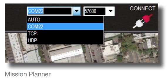
  • In Mission Planner and APM Planner ground station applications, select the communication option that shows COM, set the rate to 57600, and select Connect.
  • The radio will not connect unless the vehicle is powered. 
  • Use the Flight Data screen to view your vehicle’s status and control missions in flight.
You can learn more about how the missing planner works by visiting the manual at planner.ardupilot.com.
Picture
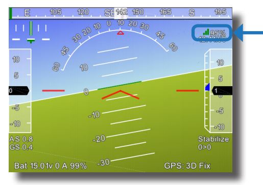
  • You can view the strength of the radio signal in the mission planner’s flight data screen
Orient the ground radio antenna vertically for maximum range.

Connecting to a Android Tablet

Picture
Picture
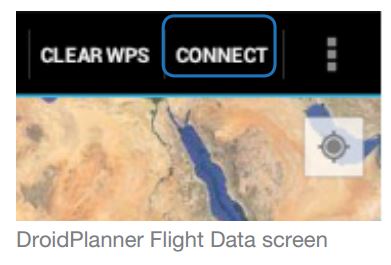
  • There are currently two android apps that you can download onto your device.  DroidPlanner and Andropilot.
  • Once the application has been installed on your device, open it.
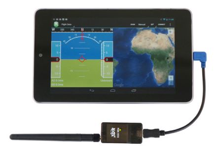
  • Connect the ground module to your tablet using the Android adapter cable.
  • Connect the colored end to the tablet and the black end to the radio.

Radio Settings (via mission planner software)

Picture
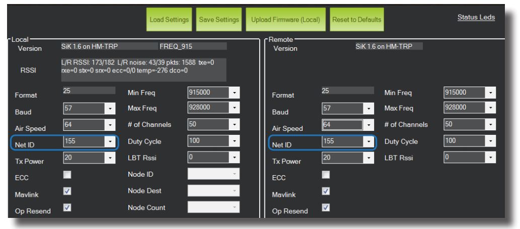
Radio Settings screen in the mission planner
For full details on all of the radio settings, please visit this page
  • To change the radio settings in the mission planner, connect the radio to your computer, but do not select Connect.
  • Radios can only be configured while unconnected to MAVLink. 
  • Select Initial Setup, 3DR Radio, and Load Settings to configure the radios
  • All settings should be the same for both modules. 
  • Ensure that the Net ID setting is identical on each radio to enable pairing. 
  • Select Save Settings to apply settings. 
  • For flying with friends, make sure your Net IDs do not conflict.
  • Use the configuration options on this screen to apply the correct airspace regulation requirements for your area. 
  • You are responsible for complying with all airspace regulations in your area, including frequency restrictions, power levels, and licenses.

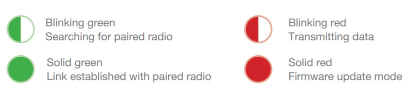
Radio module LED indicators

3DR Radio LED

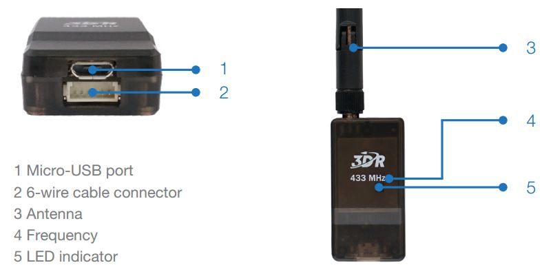
Radio Description

Picture

Radio Specifications

Processing
  • 100 mW maximum output power (adjustable)
  • -117 dBm receive sensitivity
  • Based on HopeRF’s HM-TRP module
  • RP-SMA connector
  • 2-way full-duplex communication through adaptive TDM
  • UART interface
  • Transparent serial link
  • MAVLink protocol framing
  • Frequency Hopping Spread Spectrum (FHSS)
  • Configurable duty cycle
  • Error correction corrects up to 25% of bit errors
  • Open-source SIK firmware
  • Configurable through Mission Planner & APM Planner
Features
  • Interchangeable air and ground modules
  • 433 mHz
  • Micro-USB port
  • 6-position DF13 connector


Power
  • Supply voltage: 3.7-6 VDC (from USB or DF13)
  • Transmit current: 100 mA at 30 dBm
  • Receive current: 25 mA
  • Serial interface: 3.3 V UART


Dimensions
  • 26.7 cm x 55.5 cm x 13.3 cm (without antenna)

Questions anD Support

If you have any questions you can ask them on our community forums
Visit DroneTrest
Comments
comments powered by Disqus

    Categories

    All
    Camera
    ESC
    Flight Controller
    Fpv Gear
    Gimbals
    Gluonpilot
    Multirotor
    Radio Control
    Telemetry

    RSS Feed

    Forums
    Buy Stuff
    Knowledge Base
Picture
Visit our Community Forums if you have any questions
  • Home
  • Shop
  • Students/Researchers
  • About
  • Contact
  • Manuals
  • Regulations
  • Multicopter Safety Notes
  • Blog