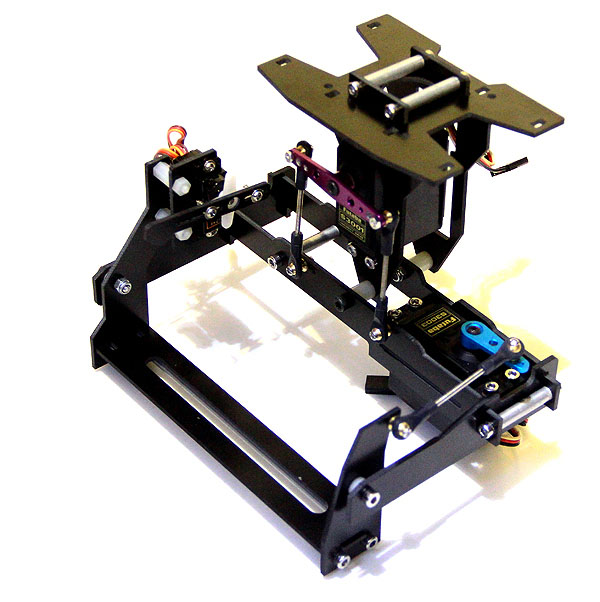
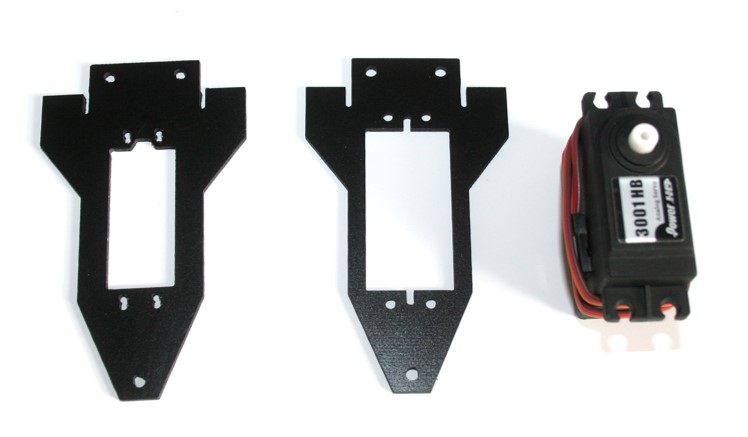
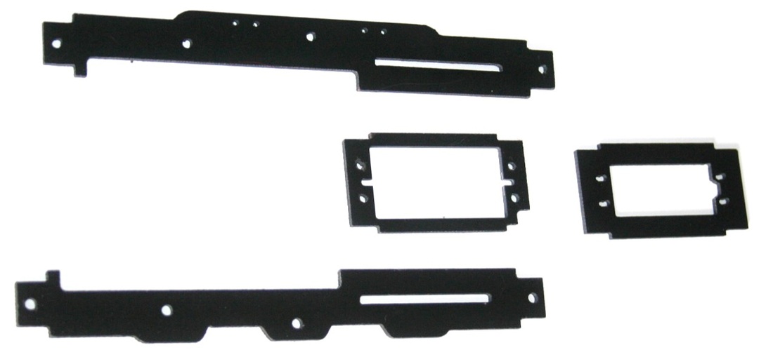
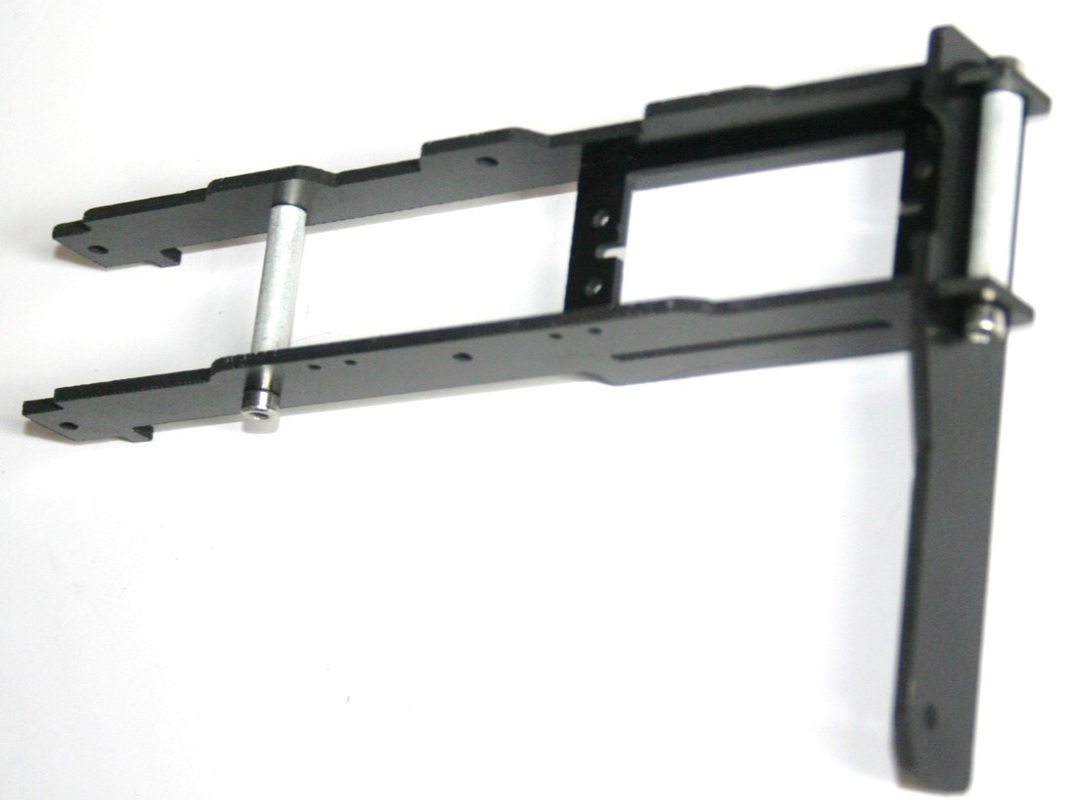
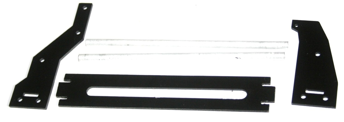
 This is a 2-axis stabilised camera mount that you can use for carrying common compact digital cameras and camcorders. This is based on the older design of our 1Kg gimbal but has been improved to make it lighter, more rigid. This gimbal also includes a special mount for a camera shutter servo (9g micro servo). This gimbal is able to stabilise both roll and pitch. This gimbal can support a few SLR cameras, but you may have difficulty using the camera servo mount. Included Parts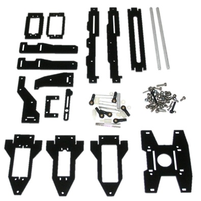 Frame Attachment Assembly
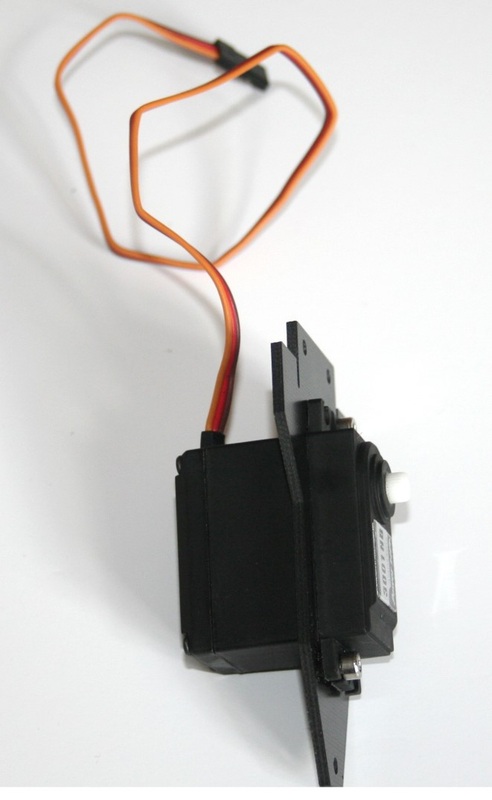
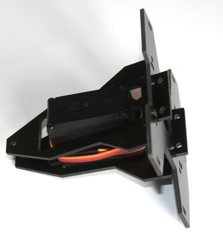
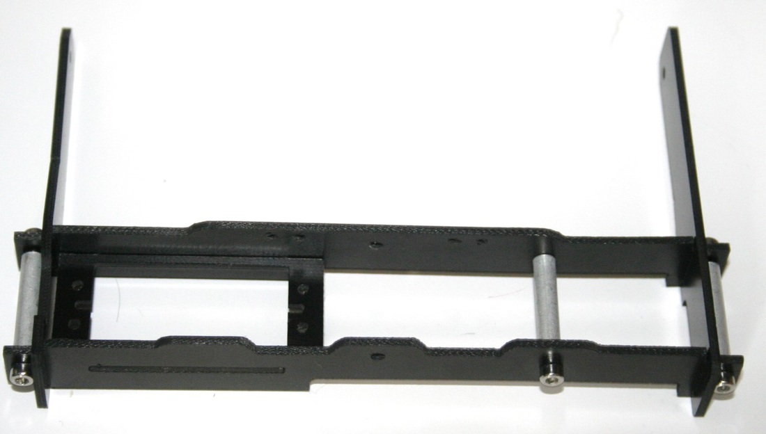
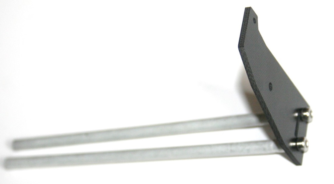
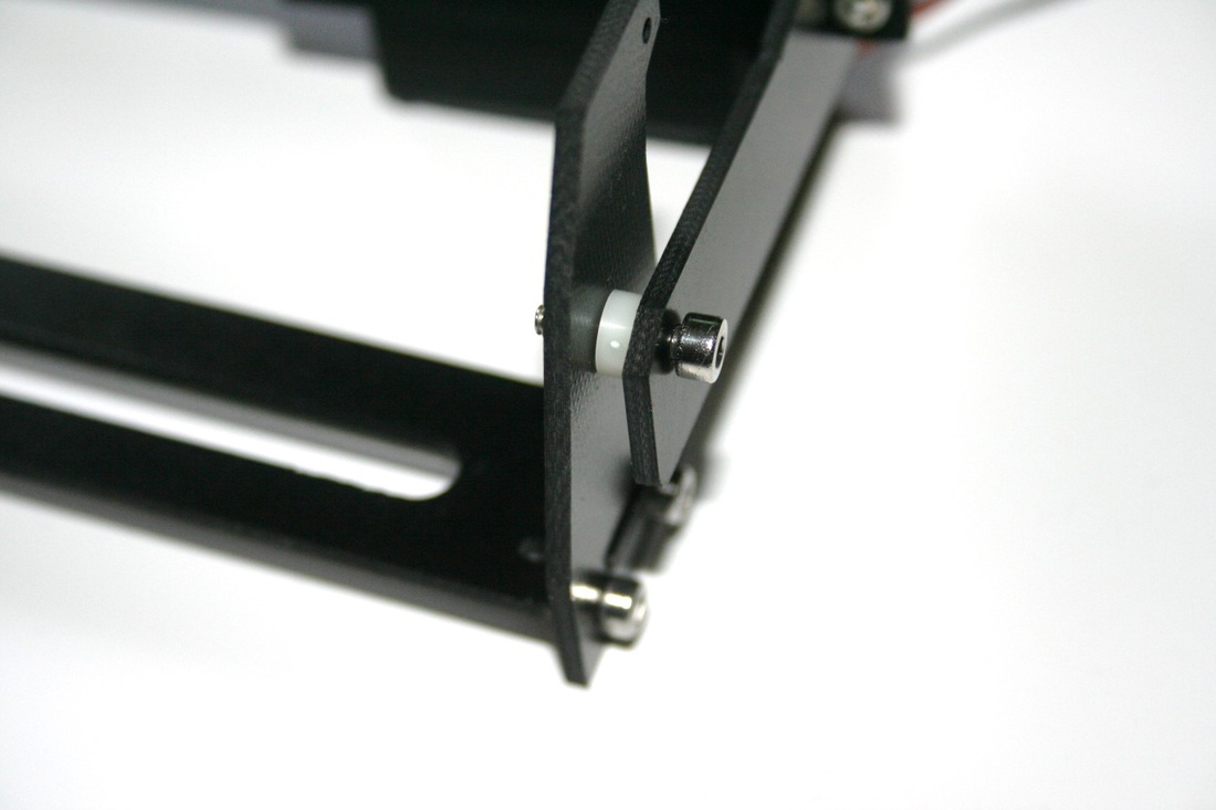
Roll Axis Assembly
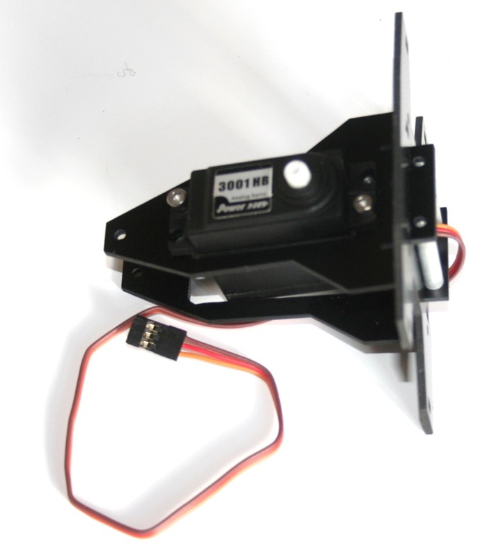
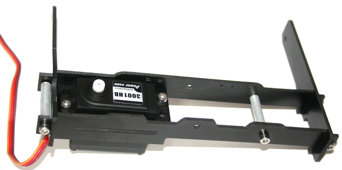
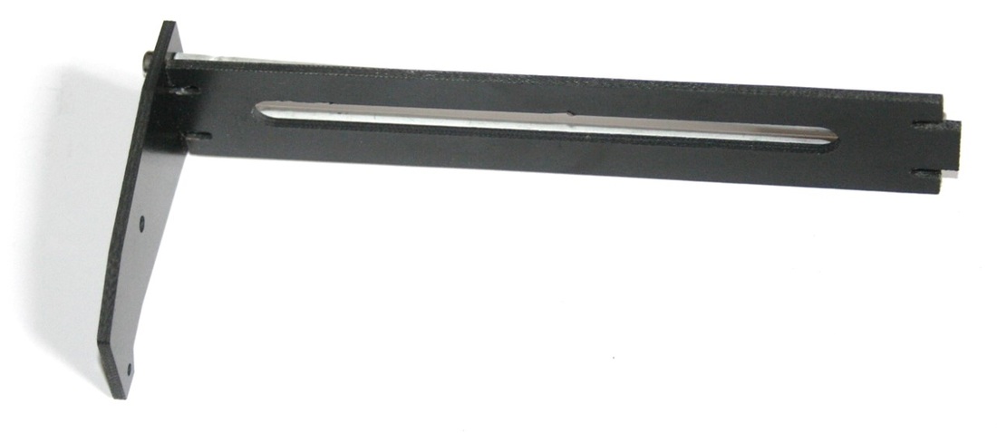
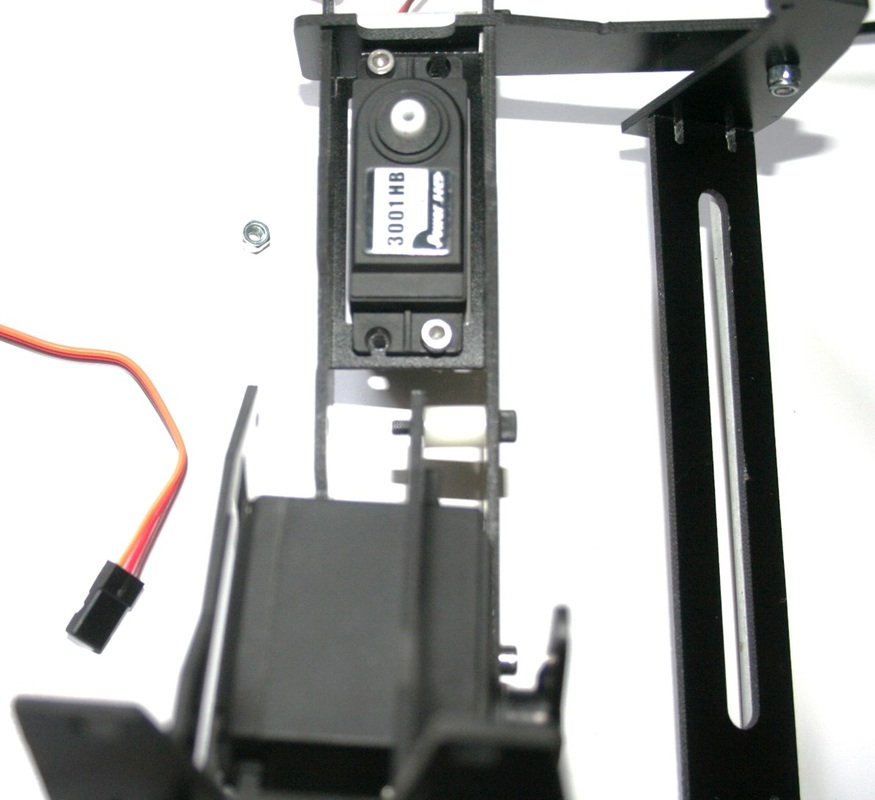
Tilt Axis Assembly
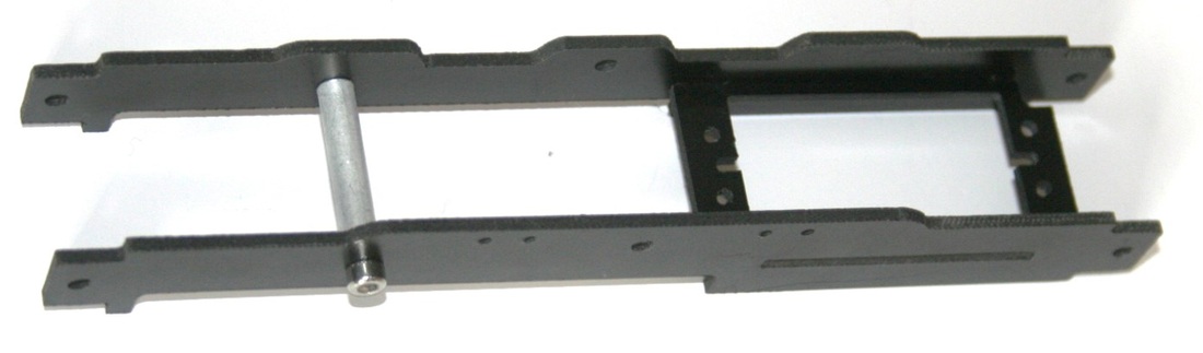
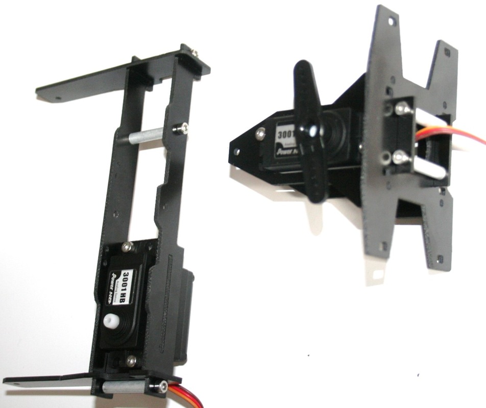
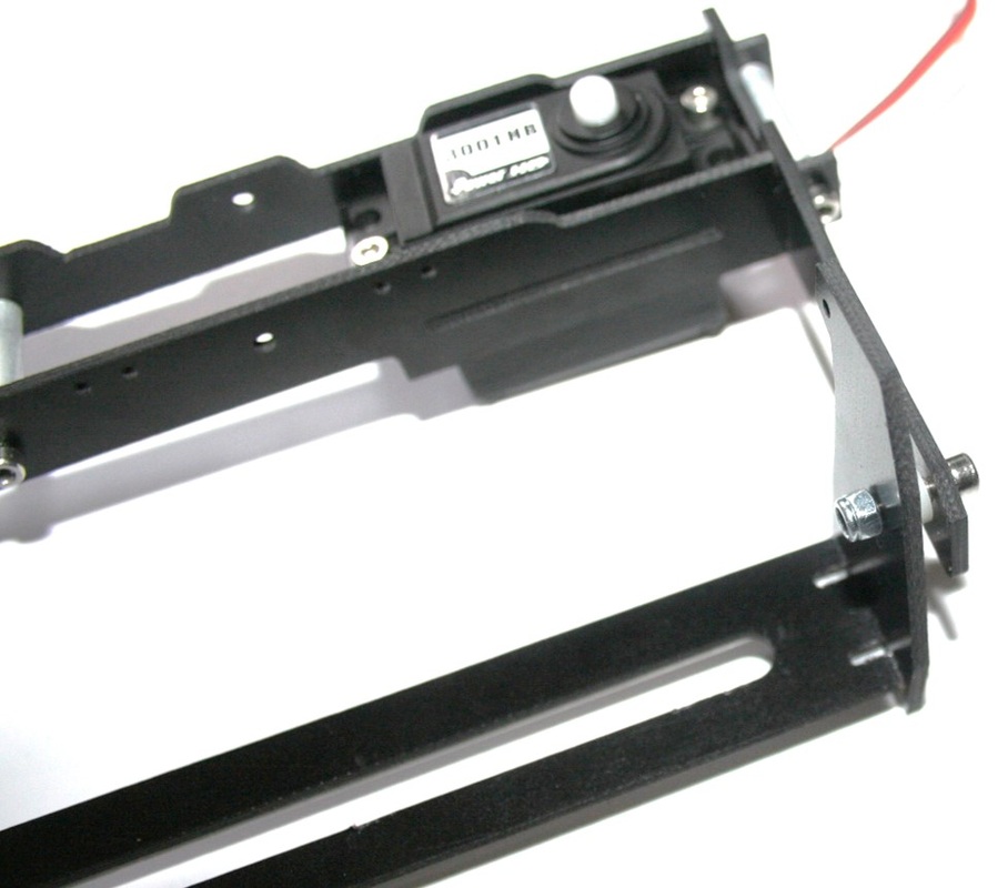
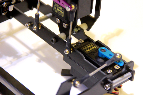
Attaching Roll Axis
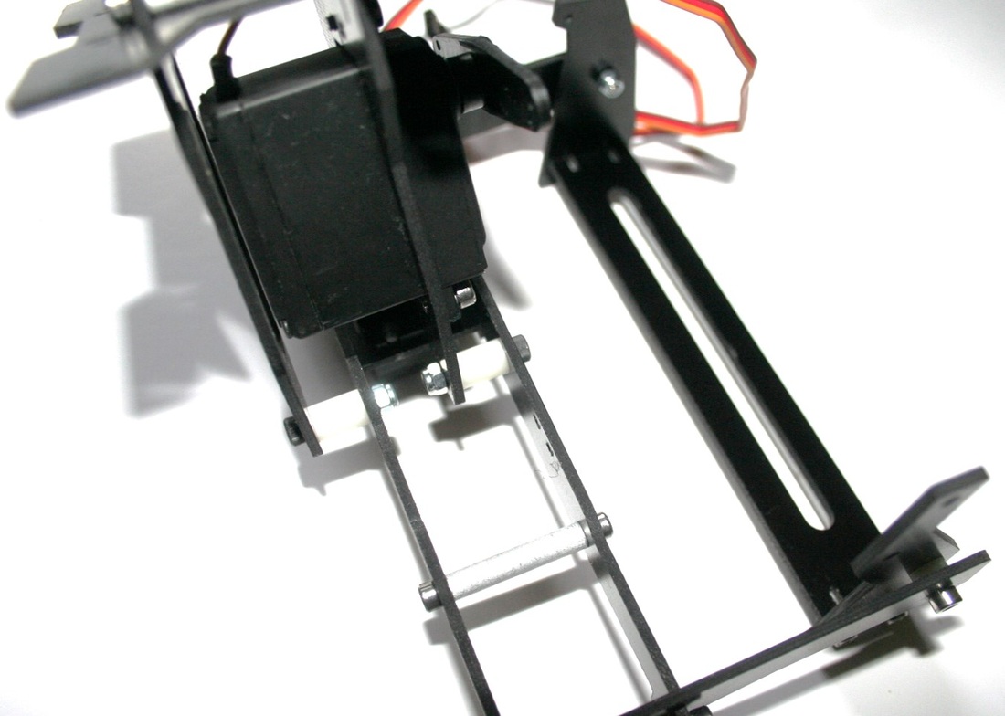
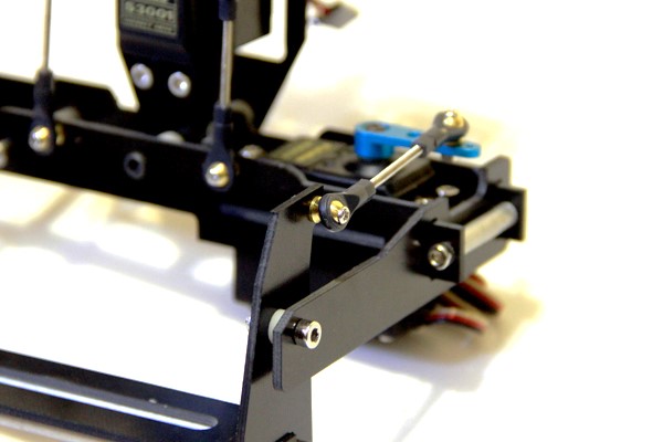
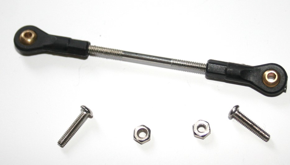
Servo Pushrod Connection
 If you have any questions please ask them below
Comments
|


 RSS Feed
|
|
Visit our Community Forums if you have any questions
|