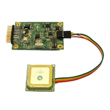
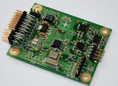
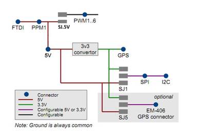
 This guide will walk you through the process of assembling and soldering your GluonPilot UAV autopilot Soldering the ConnectionsTo assemble the GluonPilot module you will need a soldering iron and some solder, however if you do not want to do this you can get a pre soldered version from the UK store, or from Belgium 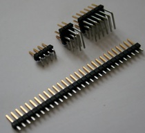 With your GluonPilot Kit, you will recieve some right angle headers, and some straight headers. The small 4x1 right angle header is used for the GPS connection, The 6x3 right angle header is used for the servo outputs. The last right angle header is used for PWM inputs. The straight headers should break apart, but it is recommended you use some cutters to snip them neatly. Cut a row of 6 headers for the FTDI cable so that you can program and configure your module. If you want you can put straight headers in all the other pins if you need them for things such as powering the module by a separate battery, or using the GluonPilot extension board. Solder the headers as shown in the image below. If you want to use servo outputs 7 and 8, you will need to solder another 2 straight male header pins on those pins. These servos will require power via a BEC as GluonPilot does not provide power to PWM outputs 7 and 8 Powering GluonPilot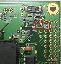 When you are programming and configuring your module, it will be powered via the FTDI cable. There are two ways to power your GluonPilot module when it is onboard your UAV. Gluonpilot requires a 5V input (+-2.5%).
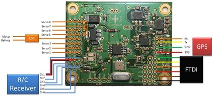
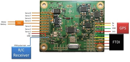
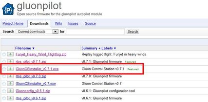
Connecting everything on GluonPilotGluonPilot supports PWM, or PPM input. Most receivers operate with PWM, and the image below shows to connect everything together if you are going to be using PWM. Your Motor/ESC is connected to the output 4 connector. Connecting everything with PWM Connecting everything with PPM (advanced users) Some hacked receivers use PPM, allowing you to connect your receiver with fewer cables. This is only reccomended for advanced users, for more information see this page Connecting with your PCNow that everything is connected, you will need to connect it to your PC to configure the module. The first step it to download the latest configuration software from here - http://code.google.com/p/gluonpilot/downloads/list Download the latest version of the GluonCSInstaller. Downloading FTDI drivers If you are using windows 7 the drivers for the FTDI cable should be installed automatically, however if not they can be downloaded here Connecting via FTDI cable 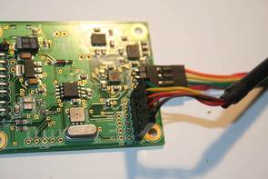 Plug your FTDI cable into your module with the black cable on the bottom of the board as shown. Now you can configure your module, or update the firmware, for more information see the next guide on how to configure and update your GluonPilot Module
Comments
|
 RSS Feed
