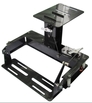
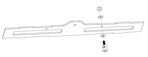
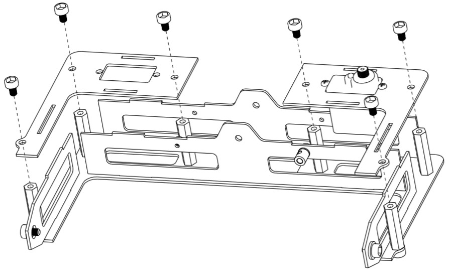
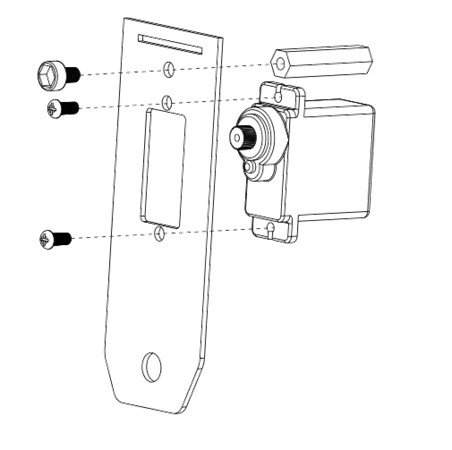
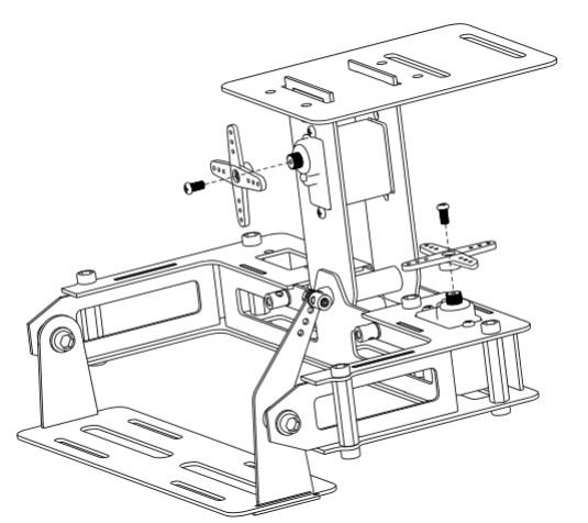
 This guide will show you how to assemble your 2 axis camera gimbal. This gimbal is designed to be used with our UT-Q650 quadcopter frame The Q650/Q800 Gimbal is a 2 axis (roll and pitch) gimbal specially designed for FPV, and aerial photography. It is compatible with the Q650 quadcopter frame. 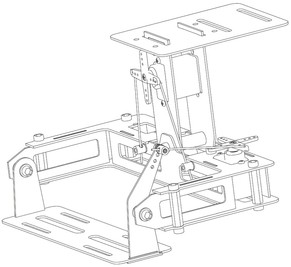 This gimbal comes with 2 digital servos which provide smooth and high precision control. A flight controller is required to use the stabilisation function. However If you don’t have one you can directly control the servos via your transmitter. Important: You will need to use some thread lock to ensure the screws do not vibrate loose. X-Axis Assembly
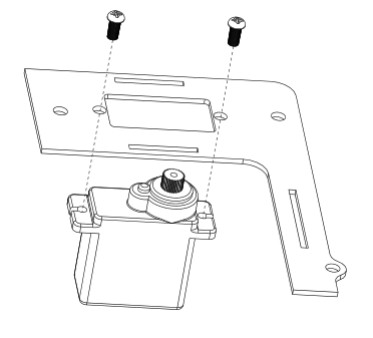
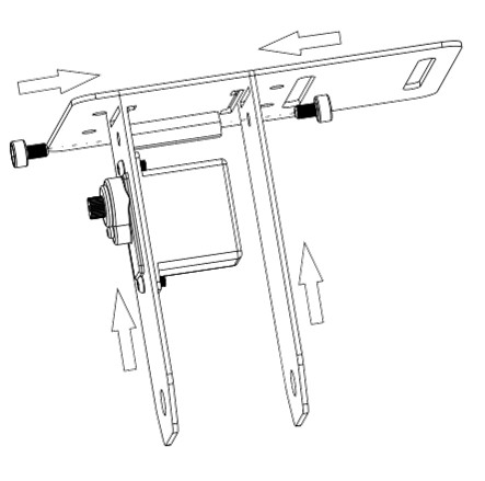
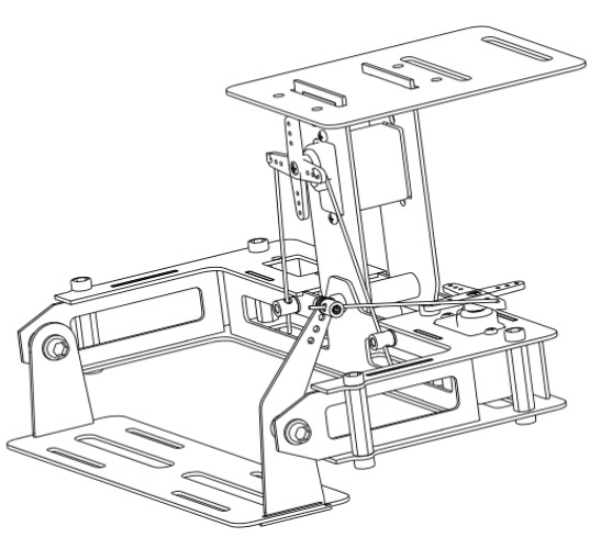
Y-Axis Assembly
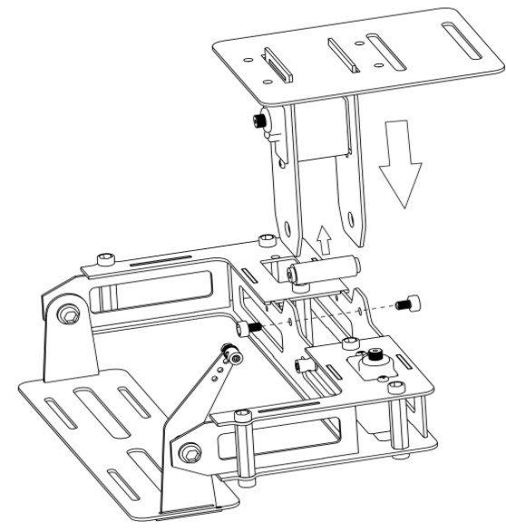
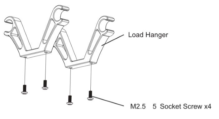
The Final Steps
If you have any comments or questions please ask them below, or on our forums.
Comments
|

 RSS Feed
|
|
Visit our Community Forums if you have any questions
|